Showing posts with label Storage. Show all posts
Is WAFL a Filesystem? - by Dave hitz  

Many people think WAFL is a filesystem. I certainly thought so fifteen years ago when I wrote it, but folks like Kostadis Roussos are now claimingthat I was wrong. (A NetApp employee no less!)

To understand why, you have to understand how WAFL is structured. 

WAFL has a “top-half” that deals with files and folders—“My Documents” and “QuarterlyEarnings.ppt”. It keeps track of who created the file, when they created it, who can look at the file, who can modify it, and so on. This certainly sounds like what a filesystem would do. The top-half actually supports multiple filesystem protocols. We started with NFS for UNIX, but right from the beginning we knew we’d be adding more. Originally we expected that Novell Netware would be next, but Windows CIFS gained momentum so quickly that we did that instead and never got around to Netware. 

WAFL also has a “bottom-half” that manages the physical disks in the system. It organizes the disks into separately managed pools, it keeps track of which disks are part of which RAID array, and it arranges data on the disk to maximize read and write performance. The “bottom half” also handles data management functions like snapshots, remote mirrors, cloning, de-duplication, thin provisioning, and so on. These capabilities would traditionally be part of a volume manageror a block virtualization layer.

One of the things that was unique about WAFL when we shipped it was the way we integrated the two layers. There are many opportunities for new features and clever optimization if you design the layers to work well together.

When we decided to support iSCSI and Fibre Channel SAN, WAFL’s bottom-half data management capabilities were a perfect fit. In fact, one of the things that helped convince me that NetApp should support block-based storage was realizing how valuable our data management features would be in that environment. 

This top-half/bottom-half structure explains the confusion about WAFL. My current view is that WAFL contains a filesystem, multiple filesystems actually, but that’s different from being a filesystem.
Read more!

EMC SAN Architecture

This document will be using the EMC symmetrix configuration. There are a number of EMC Symmetrix configurations but they all use the same architecture as detailed below.. 
 
Front End Director Ports (SA-16b:1)
Front End Director (SA-16b)
Cache
Back End Director (DA-02b)
Back End Director Ports (DA-02b:c)
Disk Devices


Front End Director
A channel director (front end director) is a card that connects a host to the symmetrix, each card can have upto four ports.


Cache
Symmetrix cache memory buffers I/O transfers between the director channels and the storage devices. The cache is divided up into regions to eliminate contension.


Back End Director
A disk director (back end director) transfers data from disk to cache. Each back-end director can have upto four interfaces (C,D,E and F). Each back-end director interface can handle seven SCSI ids (0-6)


Disk Devices
The disk devices that are attached to the back-end directors could be either SCSI or FC-AL.


Interconnect
The direct matrix interconnect is a matrix of high speed connections to all componentswith bandwidth up to 64Gb/s


Symmetrix DMX Architecture core components are:
Channel Directors - for host communication.
Disk Directors - for Disk communication.
Global Memory Directors - for I/O delivery from hosts to Disk Directors.


SAN Components

The are many components to a SAN Architecture. A host can connect to a SAN via direct connection or via a SAN switch.
Host HBA Host bus adaptor cards are used to access SAN storage systems
SAN Cables There are many types of cables and connectors:

Types: Multimode (<500m), single mode (>500m) and copper
Connectors: ST, SC (1Gb), LC (2Gb)
SAN Switches The primary function of a switch is to provide a physical connection and logical routing of data frames between the attached devices.
Support multiple protocols: Fibre channel, iSCSI, FCIP, iFCP
Type of switch: Workgroup, Directors
SAN Zoning Zoning is used to partition a fibre channel switched fabric into subsets of logical devices. Each zone contains a set of members that are permitted to access each other. Members are HBA's, switch ports and SAN ports.
Types of zoning: hard, soft and mixed
Zone set s This is a group of zones that relate to one another, only one zone set can be active at any one time.
Storage arrays Storage array is were all the disk devices are located.
Volume access control This is also know as LUN masking. The storage array maintains a database that contains a map of the storage volumes and WWN's that are allowed to access it. The VCM database in a symmetrix would contain the LUN masking information.

SAN Login

The below table documents the various proccesses that occur when a fibre channel device is connected to a SAN
Information/process FLOGI (fabric login) PLOGI (port login) PRLI (process login)
What is need ? - Link initialization
- Cable
- HBA and driver
- Switch Port
- FLOGI
- Zoning
- Persistent binding
- Driver setting
- PLOGI
- Device masking (target)
- Device mapping (initiator)
- Driver setting (initiator)
What information is passed - WWN
- S_ID
- Protocol
- Class
- Zoning
- WWN
- S_ID
- ULP
- Class
- BB Credit
- LUN
Who does the communication ? - N_port to F_port - N_port to N_port - ULP( scsi-3 to scsi-3)
where to find the information ? Unix
- syslog
- switch utilites
Windows
- Event viewer
- Switch viewer
Unix
- Syslog
- Driver Ulitities
Windows
- Driver utilities
Unix
- Syslog
- Host based volume management
Windows
- Driver Utilities
- Host based volume management
- Device Manager
If any one of the above were to fail then the host will not be allowed to access the disks on the SAN.

VCM Database
The Symmetrix Volume Configuration Management (VCM) database stores access configurations that are used to grant host access to logical devices in a Symmetrix storage array.
The VCM database resides on a special system resource logical device, referred to as the VCMDB device, on each Symmetrix storage array.
Information stored in the VCM database includes, but is not limited to:
  • Host and storage World Wide Names
  • SID Lock and Volume Visibility settings
  • Native logical device data, such as the front-end directors and storage ports to which they are mapped
Masking operations performed on Symmetrix storage devices result in modifications to the VCM database in the Symmetrix array. The VCM database can be backed up, restored, initialized and activated. The Symmetrix SDM Agent must be running in order to perform VCM database operations (except deleting backup files).
Switches
There are three models of switchs M-series (Mcdata), B-series (Brocade) and the MDS-series (Cisco). Each of the switch offer a web interface and a CLI. The following tasks can be set on most switches:
  • Configure network params
  • Configure fabric params (BB Credit, R_A_TOV, E_D_TOV, switch PID format, Domain ID)
  • Enable/Disable ports
  • Configure port speeds
  • Configure Zoning
BB Credit Configure the number of buffers that are available to attached devices for frame receipt default 16. Values range 1-16.
R_A_TOV Resource allocation time out value. This works with the E_D_TOV to determine switch actions when presented with an error condition
E_D_TOV Error detect time out value. This timer is used to flag potential error condition when an expected response is not received within the set time
The CLI commands can be viewed here for all switches, also a detailed view of zoning can be located here.
Host HBA's
The table below outlines which card will work with a particular O/S
Solaris Emulex PCI (lputil)
Qlogic
HPUX PCI-X gigabit fibre channel and ethernet card
AIX FC6227/6228/6239 using IBM native drivers
Windows Emulex (HBAnyware or lputilnt)
Linux Emulex PCI (lputil)
Read more!

How do I add a disk to a VG in an active Metrocluster ( CA/XP )

How do I add a disk to a VG in an active Metrocluster (CA/XP)?
# These items are as I used them on my system
# Substitute with your own values!!!!!!!!!
# HORCMINST : 200
# dev_group : p01oms
# dev_name : p01oms_00, p01oms_01, p01oms_02 etc...

# Export the HORCM instance number you want to work with

->  export HORCMINST=200

1. Find spare disk
*** Hint: use xpinfo -i and raidscan -p -fx, pvdisplay and/or strings the lvmtab file 

2. pvcreate disk 

3. Add disk to /etc/horcm(?).conf on local system 
(Just follow the standard in the file) 

4. Add disk to /etc/horcm(?).conf on remote system 

5. Stop / start raidmanager (local and remote) 
(Note: This is to re-read the config file and does not affect the running packages or cluster) 

-> horcmshutdown.sh 200
-> horcmstart.sh 200 

7:  Check using pairdisplay -g xxxxx -fx (disks will show SMPL) 
->pairdisplay -g p01oms -fx | more 

8:  paircreate the new disks 
# Syntax: paircreate -g -vl -f -c

 -> paircreate -g p01oms p01oms_25 -vl -c 15 -f data
 -> paircreate -g p01oms p01oms_26 -vl -c 15 -f data 

9. Check the status with pairdisplay
->pairdisplay -g p01oms -fx # (Will show COPY) 

10. vgextend vg's on local host 

11. Do a pairsplit 
-> pairsplit -g p01oms -rw 

12. Create mapfile with vgexport -s -p on local host and rcp to remote host 

13. On remote host, vgexport, then vgimport 

14. Do a pairresync
 ->pairresync -g p01oms -c 15
Read more!

Business Copy Pair Status Conditions

Pair Status 
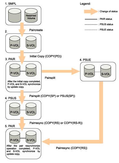
The following figure illustrates the Business Copy pair status transitions and the relationship between the pair status and the Business Copy operations. 


Figure Business Copy Pair Status Transitions 
1. If a volume is not assigned to a Business Copy pair, the volume's status is SMPL. 
2. Select the SMPL volumes for P-VOL and S-VOL to create a Business Copy pair. When you create a Business Copy pair, the initial copy operation starts. During the initial copy operation, the status of the P-VOL and S-VOL changes to COPY(PD). 
3. When the initial copy operation is complete, the pair status becomes PAIR. When the initial copy is completed, the differential data between the P-VOL and the S-VOL will be copied by the update copy. 
4. There are two kinds of pair status (PSUS and PSUE) when the pair is not synchronized. 
     • When you split a pair (pairsplit), the pair status changes to PSUS. During the pairsplit   process, the pair status becomes COPY(SP). If you specify Quick Split pairsplit, the pair status becomes PSUS(SP) during the process. When the pairsplit operation is complete, the pair status changes to PSUS to enable you to access the split S-VOL. The update copy operation is not performed on the pairs that have status PSUS. 
     • If the storage system cannot maintain PAIR status for any reason, or if you suspend the pair (pairsplit-E), the pair status changes to PSUE. 5. When you start a pairresync operation, the pair status changes to COPY(RS) or COPY(RS-R). When the pairresync operation is complete, the pair status changes to PAIR. 
     • When you specify Reverse Copy or Quick Restore mode for a pairresync operation, the pair status changes to COPY(RS-R). 
     • When you delete a pair (pairsplit-S), the status of the volumes that were used by the pair changes to SMPL. You cannot delete the pair that has status PSUS(SP). 

Business Copy Pair Status
The following table lists and describes the Business Copy pair status conditions.


Read more!

Fibre Channel Internals - Flow Control

IBM redbooks - Introduction to Storage Area Networks is a nice ebook to have, I liked the book particularly for its description on SAN Basics and FC Internals, here is an excerpt on Flow Control.

Flow control
Now that we know data is sent in frames, we also need to understand that devices need to temporarily store the frames as they arrive, and until they are assembled in sequence, and then delivered to the upper layer protocol. The reason for this is that due to the high bandwidth that Fibre Channel is capable of, it would be possible to inundate and overwhelm a target device with frames. There needs to be a mechanism to stop this happening. The ability of a device to accept a frame is called its credit. This credit is usually referred to as the number of buffers (its buffer credit) that a node maintains for accepting incoming data. 

Buffer to buffer
During login, N_Ports and F_Ports at both ends of a link establish its buffer to buffer credit (BB_Credit). Each port states the maximum BB_Credit that they can offer and the lower of the two is used.
 
End to end
At login all N_Ports establish end to end credit (EE_Credit) with each other. During data transmission, a port should not send more frames than the buffer of the receiving port can handle before getting an indication from the receiving port that it has processed a previously sent frame.
 
Controlling the flow
Two counters are used to accomplish successful flow control: BB_Credit_CNT and EE_Credit_CNT, and both are initialized to 0 during login. Each time a port sends a frame it increments BB_Credit_CNT and EE_Credit_CNT by one. When it receives R_RDY from the adjacent port it decrements BB_Credit_CNT by one, and when it receives ACK from the destination port it decrements EE_Credit_CNT by one. If at any time BB_Credit_CNT becomes equal to the BB_Credit or EE_Credit_CNT equal to the EE_Credit of the receiving port, the transmitting port has to stop sending frames until the respective count is decremented. The previous statements are true for Class 2 service. Class 1 is a dedicated connection, so it does not need to care about BB_Credit and only EE_Credit is used (EE Flow Control). Class 3 on the other hand is an unacknowledged service, so it only uses BB_Credit (BB Flow Control), but the mechanism is the same on all cases.

Performance
Here we can see the importance that the number of buffers has in overall performance. We need enough buffers to make sure the transmitting port can continue sending frames without stopping in order to use the full bandwidth. This is particularly true with distance. At 1 Gbps a frame occupies between about 75 m and 4 km of fiber depending on the size of the data payload. In a 100 km link we could send many frames before the first one reaches its destination. We need an acknowledgement (ACK) back to start replenishing EE_Credit or a receiver ready (R_RDY) indication to replenish BB_Credit. For a moment, let us consider frames with 2 KB of data. These occupy approximately 4 km of fiber. We will be able to send about 25 frames before the first arrives at the far end of our 100 km link. We will be able to send another 25 before the first R_RDY or ACK is received, so we would need at least 50 buffers to allow for nonstop transmission at 100 km distance with frames of this size. If the frame size is reduced, more buffers would be required to allow nonstop transmission.

Read more!

Zoning Brocade switches - Tutorial


Zoning Brocade switches - Tutorial

This tutorial provides a quick walk-through of setting up zoning on a Brocade switch. It is not a comprehensive review of the topic, but it may give you some familiarity with the commands and syntax necessary to set up zoning in the Brocade environment.

What is zoning?

Zoning provides a way to logically group together the components of a SAN. Ports, interfaces and even switches themselves can be grouped together into configurations that work together to make SANs more orderly and less daunting.

Managing configurations

All zoning in the Brocade environment is done within configurations. A configuration contains aliases and zones.

An alias is a tool to simplify repetitive port numbers or WWN entries into an easy-to-remember name. For instance: rather than typing in the WWN "50:00:0e:10:00:00:00:17" in zoning operations, one could use an alias to identify the WWN as being "DF350_intfc_0". Aliases can also be used to identify multiple ports or WWNs by a single name. All zoning commands accept aliases as valid parameters.

A zone is a set of devices that access one another. All devices connected to a Fabric may be configured into one or more zones. Devices that are in the same zone can see each other, devices that are in different zones can not.


Commands used in this example

alicreate : Creates new zone aliases. Assigns a name to a list of alias members. Alias members can include port numbers (for example; 1,2 indicates switch 1, port 2) or WorldWide? names. If there are multiple alias members, all members must be separated by semicolons within the list of alias members.

example : alicreate "df350_intfc_0", "50:00:0e:10:00:00:00:17"


zonecreate : Groups a list of zone members under a zone name. Zone members can include port numbers, WorldWide? names, or aliases created by the alicreate command. Multiple zone members must be separated by semicolons within the list of zone members.

example : zonecreate "c2zone", "snowtop_c2; df350_intfc_1"


cfgcreate : Assigns a configuration name to a list of configuration members. The configuration members are all zones Multiple configuration members are separated by semicolons.

example : cfgcreate "c2config", "c2zone"


cfgenable : Checks a specified configuration for errors and makes it the active configuration of the switch. Note: No zoning is applied to the switch until the cfgenable command completes successfully. If there is already an active configuration, cfgenable will replace the active configuration with the specified configuration.

example : cfgenable "c2config"


cfgdisable : Deactivates a specified configuration

example : cfgdisable "c2config"


cfgsave : Saves zoning information to switch's flash memory. Configuration will not survive a reboot of the switch until the configuration is saved.


cfgclear : Deactivates and removes all zoning information from active memory. To remove a configuration from flash memory, run cfgsave after cfgclear.


zoneshow : Shows zoning configuration.


switchshow : Shows overall configuration of switch. WWNs, login types (F-port, L-Port etc.) port status and some general switch info show up in switchshow.


Setting up a zoning configuration

The following example sets up a switch so that the LUNs presented on controller 0 of a DF350 Fibre unit are presented either to controller 2 or controller 3 of a Sun Solaris host depending on which configuration is activated.
Please note : If ANY ports on a switch are in an active zone configuration, ALL ports on the switch MUST be zoned in order to be useable. Since this example only uses ports 4-7 of the switch, ports 0-3 would not be useable until they were included in the active zoning configuration.

Another note : Usually it is best to zone by WWN, rather than by port number. That way, if a port goes bad the user just has to move the affected interface cable to a different port on the switch and the zoning should still be in place.


login: admin
Password:


sw2400_68:admin> switchshow
switchName: sw2400_68
switchType: 3.2
switchState: Online
switchRole: Principal
switchDomain: 1
switchId: fffc01
switchWwn: 10:00:00:60:69:20:13:c0
port 0: sw No_Light
port 1: sw No_Light
port 2: sw No_Light
port 3: sw No_Light
port 4: sw Online F-Port 50:00:0e:10:00:00:00:5d
port 5: sw Online F-Port 50:00:0e:10:00:00:00:17
port 6: sw Online F-Port 20:00:00:e0:69:c0:08:23
port 7: sw Online F-Port 20:00:00:e0:69:c0:08:45
sw2400_68:admin> alicreate "df350_intfc_0", "50:00:0e:10:00:00:00:17"
sw2400_68:admin> alicreate "df350_intfc_1", "50:00:0e:10:00:00:00:5d"
sw2400_68:admin> alicreate "snowtop_c2", "20:00:00:e0:69:c0:08:45"
sw2400_68:admin> alicreate "snowtop_c3", "20:00:00:e0:69:c0:08:23"
sw2400_68:admin> zoneshow
Defined configuration:
alias: df350_intfc_0
50:00:0e:10:00:00:00:17
alias: df350_intfc_1
50:00:0e:10:00:00:00:5d
alias: snowtop_c2
20:00:00:e0:69:c0:08:45
alias: snowtop_c3
20:00:00:e0:69:c0:08:23


Effective configuration:
no configuration in effect


sw2400_68:admin> zonecreate "c2zone", "snowtop_c2; df350_intfc_1"
sw2400_68:admin> zonecreate "c3zone", "snowtop_c3; df350_intfc_1"
sw2400_68:admin> zoneshow
Defined configuration:
zone: c2zone snowtop_c2; df350_intfc_1
zone: c3zone snowtop_c3; df350_intfc_1
alias: df350_intfc_0
50:00:0e:10:00:00:00:17
alias: df350_intfc_1
50:00:0e:10:00:00:00:5d
alias: snowtop_c2
20:00:00:e0:69:c0:08:45
alias: snowtop_c3
20:00:00:e0:69:c0:08:23


Effective configuration:
no configuration in effect


sw2400_68:admin> cfgcreate "c2config", "c2zone"
sw2400_68:admin> cfgcreate "c3config", "c3zone"
sw2400_68:admin> zoneshow
Defined configuration:
cfg: c2config
c2zone
cfg: c3config
c3zone
zone: c2zone snowtop_c2; df350_intfc_1
zone: c3zone snowtop_c3; df350_intfc_1
alias: df350_intfc_0
50:00:0e:10:00:00:00:17
alias: df350_intfc_1
50:00:0e:10:00:00:00:5d
alias: snowtop_c2
20:00:00:e0:69:c0:08:45
alias: snowtop_c3
20:00:00:e0:69:c0:08:23


Effective configuration:
no configuration in effect


sw2400_68:admin> cfgenable "c2zone"
error: "c2zone" is not a configuration
sw2400_68:admin> cfgenable "c2config"
zone config "c2config" is in effect
sw2400_68:admin> zoneshow
Defined configuration:
cfg: c2config
c2zone
cfg: c3config
c3zone
zone: c2zone snowtop_c2; df350_intfc_1
zone: c3zone snowtop_c3; df350_intfc_1
alias: df350_intfc_0
50:00:0e:10:00:00:00:17
alias: df350_intfc_1
50:00:0e:10:00:00:00:5d
alias: snowtop_c2
20:00:00:e0:69:c0:08:45
alias: snowtop_c3
20:00:00:e0:69:c0:08:23


Effective configuration:
cfg: c2config
zone: c2zone 20:00:00:e0:69:c0:08:45
50:00:0e:10:00:00:00:5d


What does this configuration look like on the Sun Solaris host?

After a reconfiguration boot, this is what the host sees when the " c2config " configuration is used on the switch.


# format
Searching for disks...done


c2t0d1: configured with capacity of 32.45GB
c2t0d2: configured with capacity of 15.51GB


AVAILABLE DISK SELECTIONS:
0. c0t0d0
/pci@1f,4000/scsi@3/sd@0,0
1. c2t0d0

/pci@6,4000/fibre-channel@2/sd@0,0
2. c2t0d1

/pci@6,4000/fibre-channel@2/sd@0,1
3. c2t0d2

/pci@6,4000/fibre-channel@2/sd@0,2


Changing the configuration
To change the configuration, simply log into the switch and activate the " c3config " configuration that we created earlier.

sw2400_68:admin> cfgenable "c3config"
zone config "c3config" is in effect


After a reconfiguration boot, the Sun Solaris host now sees the new configuration. The LUNs that used to be presented to controller 2 are now presented to controller 3:

# format
Searching for disks...done

c3t0d1: configured with capacity of 32.45GB
c3t0d2: configured with capacity of 15.51GB

AVAILABLE DISK SELECTIONS:
0. c0t0d0

/pci@1f,4000/scsi@3/sd@0,0
1. c3t0d0

/pci@6,4000/fibre-channel@3/sd@0,0
2. c3t0d1

/pci@6,4000/fibre-channel@3/sd@0,1
3. c3t0d2

/pci@6,4000/fibre-channel@3/sd@0,2


THE ABOVE TUTORIAL WAS GATHERED FROM https://tuf.hds.com/gsc/bin/view/Main/BrocadeZoning

Read more!

Glossary of Fibre Channel Terms


A

ACC
Accept Link Service reply. Accept is the normal reply to an Extended Link Service request (such as FLOGI) and indicates that the request has been completed.
ACK
Acknowledgement Frame. An ACK is used for end-to-end flow control. An ACK is sent to verify receipt of one or more frames in Class 1 and Class 2 Services.
Address Identifier
A 3-byte value typically assigned by the Fabric used to address an N_Port. Used in frames in the S_ID (source identifier) and D_ID (destination identifier) fields.
AL_PA
Arbitrated Loop Physical Address. A 1-byte value used in the Arbitrated Loop topology used to identify L_Ports. This value will then also become the last byte of the address identifier for each public L_Port on the loop
AL_TIME
Arbitrated Loop Timeout value. Twice the amount of time it would take for a Transmission Word to propagate around a worst-case Loop, i.e. a Loop with 134 L_Ports and 10 km links between each L_Port, with a 6 Transmission Word delay through each L_Port. This value is set at 15 ms.
Arbitrated Loop
One of the three Fibre Channel topologies. Up to 126 NL_Ports and 1 FL_Port are configured in a unidirectional loop. Ports arbitrate for access to the Loop based on their AL_PA. Ports with lower AL_PA's have higher priority than those with higher AL_PA's.
ARB
Arbitrate Primitive Signal. This Primitive Signal applies only to the Arbitrated Loop topology. It is transmitted as the Fill Word by an L_Port to indicate that the L_Port is arbitrating to access to the Loop.

B

BB_Credit
Buffer-to-buffer credit value. Used for buffer-to-buffer flow control, this determines the number of frame buffers available in the port it is attached to, i.e., the maximum number of frames it may transmit without receiving an R_RDY.

C

Class 1 Service
A method of communicating between N_Ports in which a dedicated connection is established between them. The ports are guaranteed the full bandwidth of the connection and frames from other N_Ports may be blocked while the connection exists. In-order delivery of frames is guaranteed. Uses end-to-end flow control only.
Class 2 Service
A method of communicating between N_Ports in which no connection is established. Frames are acknowledged by the receiver. Frames are routed through the Fabric, and each frame may take a different route. In-order delivery of frames is not guaranteed. Uses both buffer-to-buffer flow and end-to-end flow control.
Class 3 Service
A method of communicating between N_Ports similar to Class 2 service, except there is no acknowledgment of received frames. Frames are routed through the Fabric as in Class 2, and in-order delivery is not guaranteed. Uses only buffer-to-buffer flow control.
CLS
Close Primitive Signal. This Primitive Signal applies only to the Arbitrated Loop topology. It is Primitive Signal is sent by an L_Port which is currently communicating on the Loop (i.e., it has won access to the loop or was opened by another L_Port which had won access to the Loop) to close communication with the other L_Port.

D

D_ID
Destination identifier. A 3-byte field in the frame header used to indicate the address identifier of the N_Port the frame is to be delivered to.
Disparity
The difference between the number of 1's and 0's in a Transmission Character. A Transmission Character with more 1's than 0's is said to have positive running disparity. A Transmission Character with more 0's than 1's is said to have negative running disparity. A Transmission Character with an equal number of 1's and 0's is said to have neutral disparity.

E

E_D_TOV
Error Detect Timeout value. A timer used to represent the longest possible time for a frame to make a roundtrip through the Fabric. This value is negotiated at N_Port Login and will typically be on the order of a few seconds. E_D_TOV is used to decide when some particular error recovery action must be taken.
EE_Credit
End-to-end credit value. Used for end-to-end flow control, determines the maximum number of frames that may remain unacknowledged.
EOF
End of Frame delimiter. This Ordered Set is always the last Transmission Word of a Frame. It is used to indicate that a Frame has ended and indicates whether the Frame is valid or invalid.
Exchange
The highest level Fibre Channel mechanism used for communication between N_Ports. Exchanges are composed of one or more related sequences. Exchanges may be bidirectional or unidirectional.

F

Fabric
One of the three Fibre Channel topologies. In the Fabric topology, N_Ports are connected to F_Ports on a switch. Depending on vendor support, fabric switches may be interconnected to support up to 16 million+ N_Ports on a single network.
F_BSY
Fabric Port Busy Frame. This Frame is issued by the Fabric to indicate that a particular cannot be delivered because the Fabric or the destination N_Port is too busy.
FC-AL
Fibre Channel Arbitrated Loop. Refers to the ANSI FC-AL document which specifies operation of the Arbitrated Loop topology.
FC-PH
Fibre Channel Physical and Signaling Interface. Refers to the ANSI FC-PH document which specifies the FC-0, FC-1, and FC-2 layers of the Fibre Channel protocol. FC-0 Fibre Channel layer 0. Specifies the physical signalling used in Fibre Channel, as well as cable plants, media types, and transmission speeds.
FC-1
Fibre Channel layer 1. Specifies the IBM patented 8B/10B data encoding used in Fibre Channel.
FC-2
Fibre Channel layer 2. Specifies the frame format, Sequence/Exchange management, and Ordered Set usage in Fibre Channel.
FC-3
Fibre Channel layer 3. Specifies services provided for multiple N_Ports in a single node.
FC-4
Fibre Channel layer 4. Specifies mapping of Upper Level Protocols such as SCSI and IP onto the Fibre Channel Protocol.
Fill Word
The Primitive Signal is used by L_Ports to be transmitted in between Frames. This may be Idle or ARBx, depending on which, if any, L_Ports are Arbitrating for Loop access, and will not necessarily be the same for all L_Ports on the Loop at any given time.
FL_Port
Fabric-Loop port. An F_Port which is capable of supporting an attached Arbitrated Loop. An FL_Port on a Loop will have the AL_PA hex'00', giving the Fabric highest priority access to the Loop. An FL_Port is the gateway to the Fabric for NL_Ports on a Loop.
F/NL_Port
An NL_Port which is capable of providing certain Fabric services to other NL_Ports on a Loop in the absence of a Fabric. This NL_Port will respond to requests to open communication with AL_PA hex'00', even though it may actually have another value for its AL_PA.
F_Port
Fabric port. A port on a fabric switch to which N_Ports may be directly connected. An F_Port is uses the address identifier hex'FFFFFE'.
Frame
The basic unit of communication between two N_Ports. Frames are composed of a starting delimiter (SOF), a header, the payload, the Cyclic Redundancy Check (CRC), and an ending delimiter (EOF). The SOF and EOF contain the Special Character and are used to indicate where the frame begins and ends. The 24-byte header contains information about the frame, including the S_ID, D_ID, routing information, the type of data contained in the payload, and sequence/exchange management information. The payload contains the actual data to be transmitted, and may be 0-2112 bytes in length. The CRC is a 4-byte field used for detecting bit errors in the received frame.
F_RJT
Fabric Port Reject Frame. This Frame is issued by the Fabric to indicate that delivery of a particular frame is being denied. Some reasons for issuing an F_RJT include: Class not supported; invalid header field(s); and N_Port unavailable.

G H I

Idle
An Ordered Set transmitted continuously over a link when no data are being transmitted. Idle is transmitted to maintain an active link over a fibre and lets the receiver and transmitter maintain bit, byte, and word synchronization.
Intermix
A service in which Class 2 and Class 3 frames may be delivered to an N_Port which has a Class 1 dedicated connection open. The Class 2 and 3 frames are delivered during times which no Class 1 frames are being delivered on the connection.

J K L

Link Service
Link Services are facilities used between an N_Port and a Fabric or between two N_Ports and are used to for such purposes as Login, Sequence and Exchange management, and maintaining connections.
LIP
Loop Initialization Primitive Sequence. This Primitive Sequence applies only to the Arbitrated Loop topology. It is transmitted by an L_Port to (re)initialize the Loop.
LIFA
Loop Initialization Fabric Assigned Frame. This is the first Frame transmitted in the Loop initialization process after a temporary Loop master has been selected. L_Ports which have been assigned their AL_PA by the Fabric will select their AL_PA's in this frame as it makes its way around the Loop.
LIHA
Loop Initialization Hard Assigned Frame. This is the third Frame transmitted in the Loop initialization process after a temporary Loop master has been selected. L_Ports which have been programmed to select a particular AL_PA (if available) by the manufacturer will select their AL_PA's in this frame as it makes its way around the Loop.
LILP
Loop Initialization Loop Position Frame. This is the second Frame transmitted in the Loop initialization process after all L_Ports have selected an AL_PA (after LISA has been around the loop). This Frame is transmitted around the Loop so that all L_Ports may know the relative position of all other L_Ports around the Loop. Support for this Frame by an L_Port is optional.
LIPA
Loop Initialization Previously Assigned Frame. This is the second Frame transmitted in the Loop initialization process after a temporary Loop master has been selected. L_Ports which had an AL_PA prior to the Loop initialization will select their AL_PA's in this frame as it makes its way around the Loop.
LIRP
Loop Initialization Report Position Frame. This is the first Frame transmitted in the Loop initialization process after all L_Ports have selected an AL_PA (after LISA has been around the loop). This Frame is transmitted around the Loop so that all L_Ports report their relative physical position on the loop. Support for this Frame by an L_Port is optional.
LISA
Loop Initialization Soft Assigned Frame. This is the fourth Frame transmitted in the Loop initialization process after a temporary Loop master has been selected. L_Ports which did not select an AL_PA in any of the previous Loop Initialization Frames (LIFA, LIPA, or LIHA) will select their AL_PA's in this frame as it makes its way around the Loop.
LISM
Loop Initialization Select Master Frame. This Frame applies only to the Arbitrated Loop topology. It is the first frame transmitted in the initialization process in which L_Ports select an AL_PA. It is used to select a temporary Loop master, or the L_Port that will subsequently initiate transmission of the remaining initialization frames (LIFA, LIPA, LIHA, LISA, LIRP, and LILP).
LPB
Loop Port Bypass Primitive Sequence. This Primitive Sequence applies only to the Arbitrated Loop topology. It is transmitted by an L_Port to bypass the L_Port it is directed to. For example, if Port A suspects that Port B is malfunctioning, Port A can send an LPB to Port B so that Port B will only retransmit everything it receives, and will not be active on the Loop.
LPE
Loop Port Enable Primitive Sequence. This Primitive Sequence applies only to the Arbitrated Loop topology. It is transmitted by an L_Port to enable an L_Port which has been bypassed with the LPB Primitive Sequence.
L_Port
Loop port. Generic term for an NL_Port or FL_Port, i.e., any Fibre Channel port which supports the Arbitrated Loop topology.
LPSM
Loop Port State Machine. This is a state machine maintained by an L_Port to track its behavior through different phases of Loop operation, i.e., how it behaves when it is arbitrating for Loop access, how it behaves when it has control of the Loop, etc.
LR
Link Reset Primitive Sequence. This Primitive Sequence is used during link initialization between two N_Ports in the Point-to-point topology or an N_Port and an F_Port in the Fabric topology. The expected response to a port sending LR is the LRR Primitive Sequence.
LRR
Link Reset Response Primitive Sequence. This Primitive Sequence is used during link initialization between two N_Ports in the Point-to-point topology or an N_Port and an F_Port in the Fabric topology. It is sent in response to the LR Primitive Sequence. The expected response to a port sending LRR is Idle.

M

MRK
Mark Primitive Signal. This Primitive Signal applies only to the Arbitrated Loop topology. It is transmitted by an L_Port for synchronization purposes and its use is vendor specific.

N

NL_Port
Node-Loop port. An N_Port which can operate on the Arbitrated Loop topology.
Nonparticipating Mode
An L_Port will enter the nonparticipating mode if there are more than 127 devices on a Loop, and it thus cannot acquire an AL_PA. An L_Port may also voluntarily enter the nonparticipating mode if it is still physically connected to the Loop, but wishes not to participate. An L_Port in the nonparticipating mode is not capable of generating Transmission Words on the Loop and may only retransmit words received on its inbound fibre.
NOS
Not Operational Primitive Sequence. This Primitive Sequence is used during link initialization between two N_Ports in the Point-to-point topology or an N_Port and an F_Port in the Fabric topology. It is sent to indicate that that transmitting port has detected a link failure or is offline. The expected response to a port sending NOS is the OLS Primitive Sequence.
N_Port
Node port. A port on a computer, disk drive, etc. through which the device does its Fibre Channel communication.
N_Port Name
An 8-byte manufacturer-assigned value which uniquely identifies the N_Port throughout the world.

O

OLS
Offline Primitive Sequence. This Primitive Sequence is used during link initialization between two N_Ports in the Point-to-point topology or an N_Port and an F_Port in the Fabric topology. It is sent to indicate that the transmitting port is attempting to initialize the link, has recognized the NOS Primitive Sequence, or is going offline. The expected response to a port sending OLS is the LR Primitive Sequence.
OPN
Open Primitive Signal. This Primitive Signal applies only to the Arbitrated Loop topology. The OPN Primitive Signal is sent by an L_Port that has won the arbitration process to open communication with with one or more other ports on the Loop.
Ordered Set
A 4-byte Transmission Word which has the Special Character as its first Transmission Character. An Ordered Set may be a Frame Delimiter, a Primitive Signal, or a Primitive Sequence. Ordered Sets are used to distinguish Fibre Channel control information from data.
Originator
The N_Port which originated an Exchange.
OX_ID
Originator Exchange Identifier. A 2-byte field in the frame header used by the originator of an Exchange to identify frames as being part of a particular Exchange.

P

Participating Mode
The normal operating mode for an L_Port on a Loop. An L_Port in this mode has acquired an AL_PA and is capable of communicating on the Loop.
Primitive Sequence
An Ordered Set transmitted repeatedly and used to establish and maintain a link. LR, LRR, NOS, and OLS are Primitive Sequences used to establish an active link in a connection between two N_Ports or an N_Port and an F_Port. LIP, LPB, and LPE are Primitive Sequences used in the Arbitrated Loop topology for initializing the Loop and enabling or disabling an L_Port.
Primitive Signal
An Ordered Set used to indicate an event. Idle and R_RDY are used in all three topologies. ARB, OPN, CLS, and MRK are used only in the Arbitrated Loop topology.
Private Loop
An Arbitrated Loop which stands on its own, i.e., it is not connected to a Fabric.
Private NL_Port
An NL_Port which only communicates with other ports on the loop, not with the Fabric. Note that a Private NL_Port may exist on either a Private Loop or a Public Loop.
Public Loop
An Arbitrated Loop which is connected to a Fabric.
Public NL_Port
An NL_Port which may communicate with other ports on the Loop as well as through an FL_Port to other N_Ports connected to the Fabric.

Q R

Responder
The N_Port to with which an Exchange originator wishes to communicate.
RX_ID
Responder Exchange Identifier. A 2-byte field in the frame header used by the responder of the Exchange to identify frames as being part of a particular Exchange.

S

Sequence
A group of related frames transmitted unidirectionally from one N_Port to another.
SEQ_ID
Sequence Identifier. A 1-byte field in the frame header used to identify which Sequence of an Exchange a particular frame belongs to.
Sequence Initiator
The N_Port which began a new Sequence and transmits frames to another N_Port.
Sequence Recipient
The N_Port to which a particular Sequence of data frames is directed.
S_ID
Source Identifier. A 3-byte field in the frame header used to indicate the address identifier of the N_Port the frame was sent from.
SOF
Start of Frame delimiter. This Ordered Set is always the first Transmission Word of a Frame. It is used to indicate that a Frame will immediately follow and indicates which class of service the Frame will use.
Special Character
A special 10-bit Transmission Character which does mot have a corresponding 8-bit value, but is still considered valid. The Special Character is used to indicate that a particular Transmission Word is an Ordered Set. The Special Character is the only Transmission Character to have 5 1's or 0's in a row. The Special Character is also referred to as K28.5 when using K/D format.

T

Transmission Character
A (valid or invalid) 10-bit character transmitted serially over the fibre. Valid Transmission Characters are determined by the 8B/10B encoding specification.
Transmission Word
A string of four consecutive Transmission Characters.

U

ULP
Upper Level Protocol. The protocol which runs on top of Fibre Channel through the FC-4 layer. Typical ULPs running over Fibre Channel are Small Computer System Interface (SCSI), Internet Protocol (IP), High Performance Parallel Interface (HIPPI), and Intelligent Peripheral Interface (IPI). 


V W X Y Z #

8B/10B

The IBM patented encoding method used for encoding 8-bit data bytes to 10-bit Transmission Characters. Data bytes are converted to Transmission Characters to improve the physical signal such that the following benefits are achieved: bit synchronization is more easily achieved, design of receivers and transmitters is simplified, error detection is improved, and control characters (i.e., the Special Character) can be distinguished from data characters.

Read more!

Classes of Service


Fibre Channel defines several communication strategies called Classes of service. The Class used greatly depends on the type of data to be transmitted. The major difference between the Classes is the types of flow control used. If two N_Ports are to communicate or if an N_Port is to successfully log into a Fabric, there must be at least 1 common Class of service supported between them, since Sequences and Exchanges must take place using a single Class of service. This information is exchanged during Fabric Login and N_Port Login.
  
Class 1
In Class 1, a dedicated connection is established between two N_Ports. Once established, the two N_Ports may communicate using the full bandwidth of the connection; no other network traffic affects this communication. Due to this, frames are guaranteed to arrive in the order in which they were transmitted. In addition, the media speeds must be the same for all links which make up the dedicated connection. Because of the nature of the dedicated connection, there is no need for buffer-to-buffer flow control; the Fabric does not need to buffer the frames as they are routed. Thus, only end-to-end flow control is used in Class 1. Class 1 would be used when the data needs to be continuous and time critical, such as voice or video.


Intermix  
Intermix is an option of Class 1 whereby Class 2 and Class 3 frames may be transmitted at times when Class 1 frames are not being transmitted. The Class 2 and Class 3 frames may or may not be destined to the same N_Port as the Class 1 frames. Both N_Ports as well as the Fabric must support Intermix for it to be used.

Class 2  
Class 2 is referred to as multiplex due to the fact that it is a connectionless Class of service with notification of delivery and non-delivery of frames. Since no dedicated connection needs to be established, a port can transmit frames to and receive frames from more than one N_Port. As a result, the N_Ports share the bandwidth of the links with other network traffic. Frames are not guaranteed to arrive in the order in which they were transmitted, except in the point-to-point or Loop topologies. Also, the media speeds may vary for different links which make up the path. Both buffer-to-buffer and end-to-end flow control are used in Class 2. Class 2 is more like typical LAN traffic, such as IP or FTP, where the order and timeliness of delivery is not so important.


Class 3  
Class 3 is very similar to Class 2. The only exception is that it only uses buffer-to-buffer flow control. It is referred to a datagram service. Class 3 would be used when order and timeliness is not so important, and when the ULP itself handles lost frames efficiently. Class 3 is the choice for SCSI.


Class 4
Class 4 provides fractional bandwidth allocation of the resources of a path through a Fabric that connects two N_Ports. Class 4 can be used only with the pure Fabric topology. One N_Port will set up a Virtual Circuit (VC) by sending a request to the Fabric indicating the remote N_Port as well as quality of service parameters. The resulting Class 4 circuit will consist of two unidirectional VCs between the two N_Ports. The VCs need not be the same speed.Like a Class 1 dedicated connection, Class 4 circuits will guarantee that frames arrive in the order they were transmitted and will provide acknowledgement of delivered frames (Class 4 end-to-end credit). The main difference is that an N_Port may have more than one Class 4 circuit, possibly with more than one other N_Port at the same time. In a Class 1 connection, all resources are dedicated to the two N_Ports. In Class 4, the resources are divided up into potentially many circuits. The Fabric regulates traffic and manages buffer-to-buffer flow control for each VC separately using the FC_RDY Primitive Signal. Intermixing of Class 2 and 3 frames is mandatory for devices supporting Class 4.

Class 5
The idea for Class 5 involved isochronous, just-in-time service. However, it is still undefined, and possibly scrapped altogether. It is not mentioned in any of the FC-PH documents.

Class 6
Class 6 provides support for multicast service through a Fabric. Basically, a device wishing to transmit frames to more than one N_Port at a time sets up a Class 1 dedicated connection with the multicast server within the Fabric at the well-known address of hex'FFFFF5'. The multicast server sets up individual dedicated connections between the original N_Port and all the destination N_Ports. The multicast server is responsible for replicating and forwarding the frame to all other N_Ports in the multicast group. N_Ports become members of a multicast group by registering with the Alias Server at the well-know address of hex'FFFFF8'. The Class 6 is very similar to Class 1; Class 6 SOF delimiters are the same as used in Class 1. Also, end-to end flow control is used between the N_Ports and the multicast server.
The following table summarizes the classes of service in Fibre Channel.


Class of service
Fibre Channel description
Class 1
Dedicated connection
In-order delivery, acknowledge first frame only
No flow control after first frame of connection
Class 2
"Connectionless
Frame switched
Out-of-order delivery possible
Acknowledge each frame
Buffer-to-buffer and end-to-end flow control for all frames"
Class 3
Frame switched
Out-of-order delivery possible
No acknowledgments

Buffer-to-buffer frame control for all frames
Class 4
Connection oriented
Virtual circuit
In-order delivery
Class 5
Reserved
Class 6
Connection oriented
Multicast service
Read more!